Lesson 4 - RREE Conventions
Objective
Within the RREE assessment process there are several conventions that guide the assessment process. It is also helpful to understand that some approaches may be done differently in other assessment protocols or by other user groups who are adopting the RREE process.
By working through this module you will:
- Be familiar with the conventions unique to the RREE process
- Be able to determine the baseline information required about a stream and its riparian area
- Know the basic stream descriptors and the metrics associated with these
Conventions used in FREP’s RREE
Healthy indicators are answered YES; Impairment is answered NO: Asserting that any one indicator is healthy (answer the statements as YES) or impaired (answer the statements as NO) is based upon the range of natural variability for reference streams and thresholds have been established relative to what these indicators should be to remain properly functioning.
Functioning condition is based on the range of natural variability: Establishing the causes for impairment (observation that an indicator is too high or too low) is an independent step in the RREE process. It is helpful for assessors to realize that sometimes the impairment is a naturally occurring condition, unrelated to the management practices. Impairment CAN be from NATURAL causes. Also, that streams are continually undergoing change; the RREE assessment process and determination of Properly Functioning Condition is to assert that impairment is when a condition is outside the range of naturally variability.
Recent means SINCE the start of activity: We refer to any impacts as being ‘recent’ if they occurred following the start date of the forest management activity. Thus we use the term ‘old’ to refer to an impact that was present prior to the forest management activity we are evaluating.
Baseline Observations
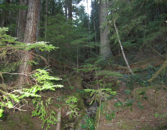
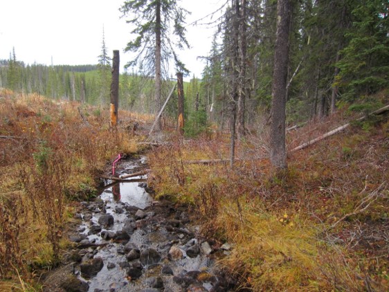
Characteristics of the stream and Description of the Riparian Retention:
On page 1 of the checklist we require baseline information that helps to characterize the stream and its riparian area for future reporting. Some of this information is required BEFORE you can start the RREE assessment process. For example, before even going to the field you need to spend office time reviewing the stream in context to the landscape and reviewing the Site Plan for riparian management practices prescribed for the stream you plan to visit. Once in the field, you must confirm the stream’s classification and determine the stream’s channel width, channel depth and channel morphology.
NOTE: Other information required for page 1 can be collected at any time during the visit to the stream but MUST be completed before you leave the site.
Determine the Stream’s Channel Morphology During a Walk Along the Reach
Pick the channel morphology that fits the most characteristics. The four characteristics of most importance:
- Bank Materials – are they fluvially sorted/layered (riffle/cascade or step-pool) or random (non-alluvial)
- Floodplains – proof the stream can move laterally, with evidence of old side channels
- Gravel bars – regularly occurring sand/gravel/cobble bars associated with stream flow and deposition
- Deposition or transport characteristics – does the stream sort and store the whole range of substrate sizes; or are larger materials affected more by gravity and fines are simply flushing out.
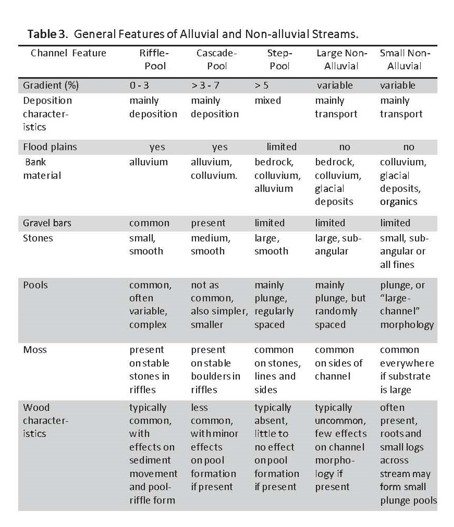
Think of this table as a voting card – the category with the most votes wins, and you record that morphology on Checklist Page 1.
Stream Reach References
Stream Reach: a section of stream to be sampled during the RREE assessment which is homogeneous for class, morphology and treatment. Where treatments are undertaken, each side of the stream must have a homogeneous treatment. For example, the left side could be logged to the banks but the right side has a timbered reserve of +100m and this is considered acceptable. In this example, if the right side had a 20m reserve for 50% of the reach length and then it has a 5m reserve for 50% of the reach length, this is NOT homogeneous and would be rejected as a viable sample.
Reach length: the sample length of homogenous stream to be sampled. The length of sample is either 30 x channel width or 100m, whichever is greater. Thus a RREE sample will always be a minimum of 100m for streams with a channel width of <3.3m. A stream that is 5m wide will require a homogenous reach length of 150m (30 x 5m).
Channel area: To estimate some of the channel features we will use channel area as the denominator for calculations. Channel area is simply the average channel width (m) x reach length (m). So a stream which is 2m wide, having a reach length of 100m has a channel area of 200m2.
Riparian zone: Within the RREE process, the 1st 10m immediately beside ALL streams is referred to as the ‘riparian zone’. Within this zone we characterize the plant community, look for invasive plants and disturbance increaser plants, look for bare erodible soil and compacted ground, levels of browse and grazing. The gross area of the riparian zone used to characterize impacts will be the reach length x 20m (10m of riparian area alongside both sides of the stream). Thus a stream which has a reach length of 100m will have a 2000m2 riparian zone.
Riparian Reserve Zone (RRZ): depending upon stream classification, some streams are managed according to default reserve zones, where logging practices are restricted. The streams with RRZ’s are S1-S3 (see table 1), and within this zone we look for signs of windthrow.
Riparian Management Zone (RMZ): depending upon stream classification, the RMZ will be either 20m or 30m. We only review the RMZ for windthrow if there was no RRZ. On streams with a RRZ, the RMZ is typically established to buffer/protect the RRZ from logging impacts and windthrow.
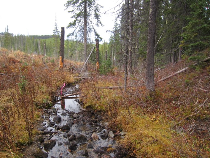
PHOTO: Example where a stream along the edge of a cutblock has 2 treatments. The left side was harvested to the banks while the right side is a fully retained forest. Each side of the stream has a homogenous treatment and is thus eligible for assessment.
Substrates
Channel Substrates: the inorganic material in a stream’s channel (the substrate) is described in varying ways, sometimes to characterize the stream and at other times we are looking for indications of rate of delivery, transport, accumulation and fish habitat quality. When describing the inorganic substrate, use the following:
Bedrock Channel bed is composed of >50% bedrock
Boulders >256 mm (larger than basketballs)
Cobbles 64-256 mm (tennis balls to basketballs)
Gravel 2-64 mm (small peppercorns to tennis balls)
Sand 0.0625-2 mm (fern spores to small peppercorns)
Fines (silts) <0.0625 mm (smaller than fern spores)
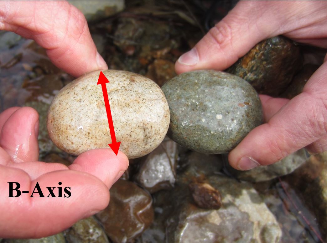
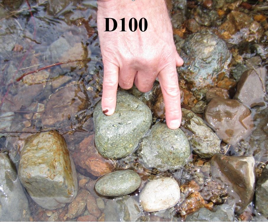
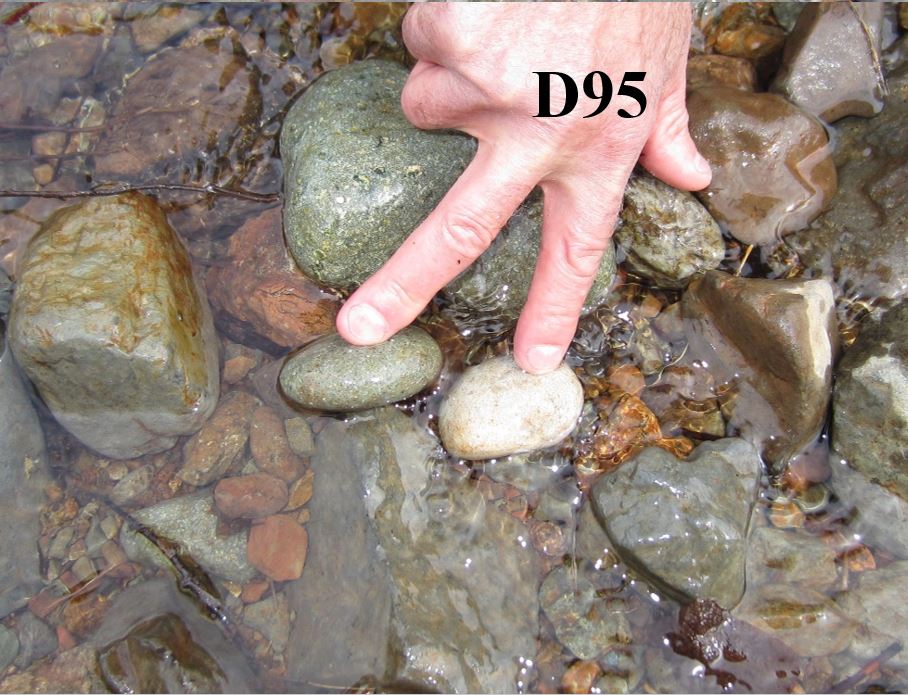
Substrate characteristics: Describing the substrate in the stream requires the assessor to determine the dominant substrate (channel roughness) and then the mobility of the substrate (D-size distributions). For the mobility measure, note that D100 represents the “largest” moveable sediment particles in the stream reach. For D95, record the mid-axis measurement (width) of the “next largest” or common category of moveable sediment particles. This should represent a piece that is larger than 95% of the remaining movable sediment particles in the channel. A D50 measurement would represent the median sized smaller moveable sediment particles.
Dominant Substrate: As you walk and/or look along the stream, what substrate class is quite common? If you see all the substrate sizes relatively equally represented, then select the largest size commonly seen (e.g., boulders). If you have bedrock, estimate the proportion of the channel that is bedrock controlled and note this on Page 1.
Heterogeneous or Homogeneous Substrates?
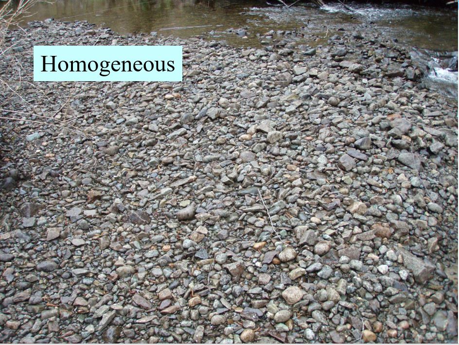
Surface Substrate Texture
For riffle/cascade-pool streams, observe the general nature of the channel bed.
If there is a wide range of sediment size classes (e.g., boulder, cobbles, gravels, sands and fines) which appear to be regularly sorted by water flows, then you will make a note for indicator Q4b on checklist page 4 that sediments are mainly heterogenous (a good thing), and select YES. If you notice that the substrate is either all one sediment size class (e.g., all cobbles) or the materials simply look randomly mixed together without sorting, then the sediments are regarded as being mainly homogenous (not so good), and you select NO to indicator Q4b.
Baseline Information (Continued): Stream Metrics
Please click on this link to view a video demonstrating how to take stream measurements
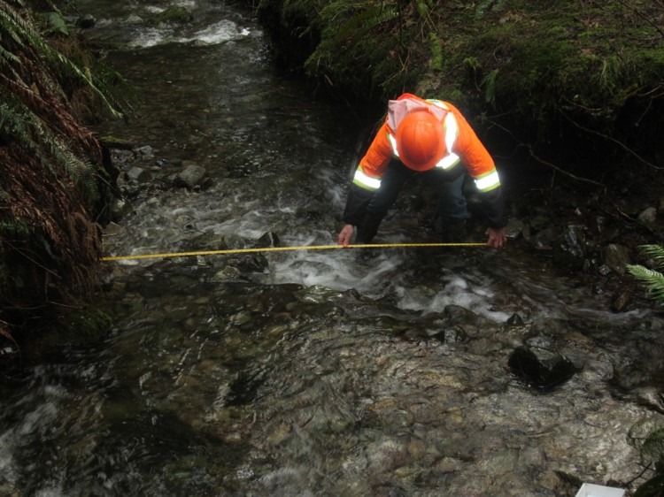
Channel width: we refer to the width of the stream as measured horizontally from the top of the rooted bank. Wetted width is the width of channel with water at the time of sampling. To determine the sampled stream’s width one takes up to 6 width measurements at undisturbed locations along the sampled reach to record the average channel width. For operational needs, a single measurement could suffice to roughly determine the length of reach required for sampling. “Rooted” width and “bank-full” width are synonymous with the term “channel” width.
Channel depth: we refer to the depth as being the deepest part of the riffle, measured vertically from the deepest part of the channel to the height of the top of the rooted bank. Wetted depth is the depth of water at this measurement position at the time of sampling.
Deep pool: a deep pool is defined as being a pool which is at least twice the depth of the stream channel compared to the depth as measured at the riffle crest below the pool feature. Note that channel depth and deep pools are measured from the substrate to the natural high-water mark on the bank and have no bearing on the actual water level at the time of sampling, thus these measurements can be made even if the channel is dry. For all stream types except for non-alluvial streams, be watchful for deep pools. If a stream is maintaining its channel morphology you should be able to find 2 deep pools. If you find a deep pool, make a notation on page 4 of the checklist, indicator Q4c.
Stream descriptions
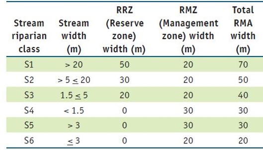
Stream description metrics: streams have a left and right side, named looking downstream. All distance measurements are slope distance (e.g., width of buffers, management and reserve zone widths).
Stream classification: We refer to stream classes on the basis of fish presence and stream width. In most cases, this is the same as the stream class on the logging plan. Record a different stream class only if the channel width clearly indicates the stream class should be different, or you have positive evidence of fish in streams designated as non-fish-bearing.
High Value S-6 stream: not all S6 stream have equal value and thus not all require the same level of management. To report on the status of high value S6 streams, we are separating the data collected. A high value S6 stream will have ONE of the following criteria:
- Directly connected to fish stream, lake or ocean (same order stream or different order and within 200m).
- Greater than 1.0 m in channel width and perennial (year-round) flow.
- Contains habitat for local species at risk.
- Drains into community watershed or water license intake (within 10km of reach sample).
- Contains other rare ecological attributes or sensitive geomorphological characteristics (e.g. alluvial fan)
NOTE: Low Value S6 does not mean it is not important and no longer requires management consideration! It still is valuable for temperature, water delivery, chemistry, nutrients, benthic invertebrate and sediment delivery to downstream reaches
Stream Order
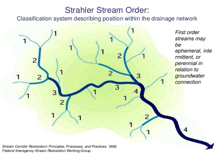
Stream Order: The stream order is the position of a stream within a watershed. We will record the stream order for the sampled reach based upon our review of the BC Watershed Atlas at 1:20,000 scale. In the RREE assessment, if a stream being sampled does not appear at this mapping scale we default record the stream as being zero (0) order.
Hillslope Failures
Hillslope failures (mass erosion): in the RREE process, we assert that an observed landslide or debris torrent may be management induced if the initiation point is within or just upslope from a block or road crossing. A road cut or block can often disrupt soil-holding capacity and the upslope slab will slump downward. This can initiate a slide that could appear to originate in the forest, but was actually caused by timber removal and/or interruption in subsurface hydrology.
Over time, head-scarps can migrate uphill, so if you are assessing a block that you suspect triggered the event, look for historical records to support your assertion that the event was management induced even though the head-scarp at the time of your visit is wholly within the timber.
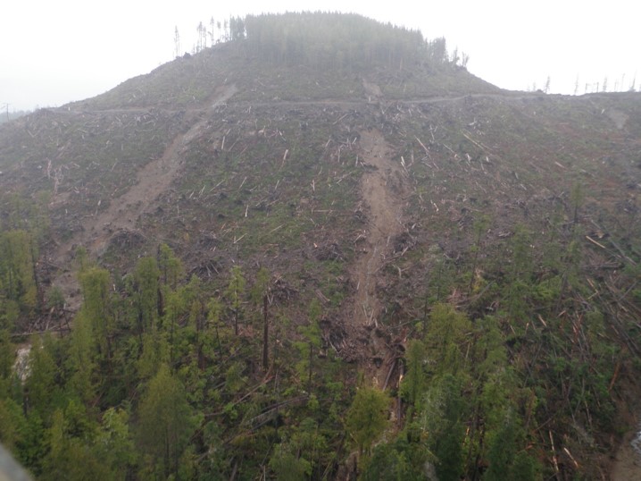
Photo of a landslide caused by road cut and block.
Undercut Banks
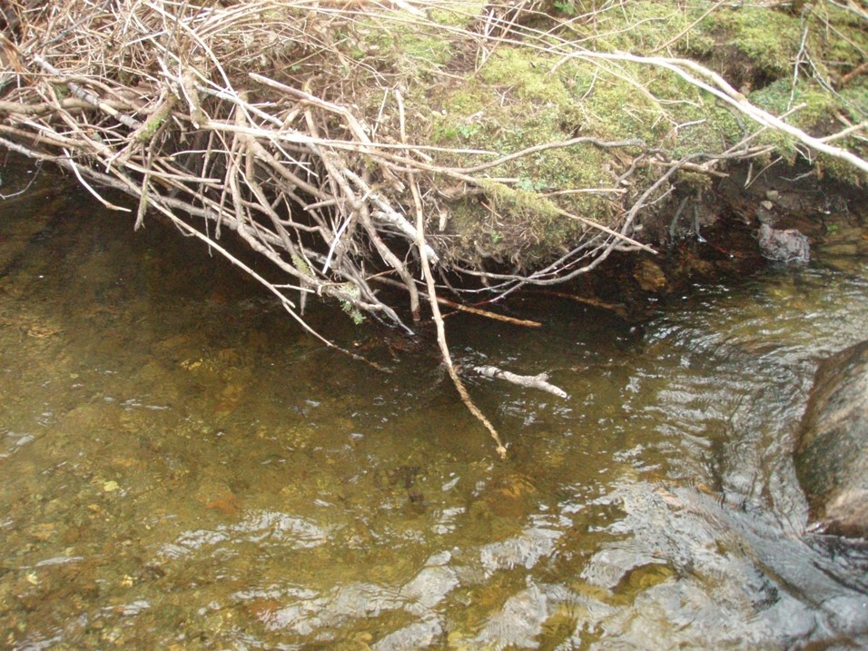
Stable undercut bank: for erodible banks, the depth of undercut required to be considered as a stable undercut bank is where the depth of undercut is 2% of the channel’s average width. A stable undercut bank must also have the top of the undercut no higher than twice this distance (i.e., 4% of channel width) above the mean annual high water mark. A stream with a channel width of 2.5m will require undercut banks to be at least 5cm depth and 10cm maximum height above the mean annual high-water mark.
Note: Non-Erodible Banks cannot be undercut. Therefore, when looking at the proportion of a reach with undercut banks you will use the ERODIBLE BANKS length as the denominator for the calculations. For example, a reach is 100m in length but has BOTH banks simultaneously Non-erodible for a 7m section. There are 27m of undercut banks measured along the reach. The proportion of the reach with stable undercut banks would be recorded as 27/(100-7)x100 = 29% .
Large Woody Debris
Large woody debris (LWD): to be considered as functioning large woody debris in a stream, the diameter of a piece of wood within the stream channel (below high-water mark) must be at least 10% of the average channel depth. A stream which is 30cm deep will require a piece of wood to be 3cm in diameter to be counted/considered eligible for tallying as LWD.
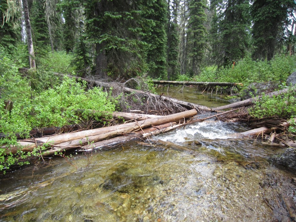
We do NOT count suspended logs as LWD; but once they collapse and a portion of the log is now in the channel, then it is considered as functioning LWD.
An accumulation of LWD is when 2 or more LWD are intertwined, and within the channel. If LWD is mobile, watch for NEW additions to existing LWD accumulations. These will have floated or fallen into the LWD accumulation and are not yet intertwined.
Old LWD is material that has been in the stream prior to the activity you are assessing. However, if the LWD is stable and incorporated into log jams, channel banks or bed, regardless of age, we consider it as OLD.
New LWD is the material that has been introduced to the stream after the activity you are assessing. Often, new LWD will be fall-down debris, logging debris, cedar shake and firewood bucking waste or windthrown trees. However, new wood could also be old wood that was once stable, but it has recently moved and is no longer stable. Look for signs of fresh erosion if you aren’t sure.
Connectivity (Part 1)
Connectivity: A stream should be able to freely transport sediment and LWD downstream and permit the movement of fish up and downstream to access the channel and habitat features.
As you work along the stream, be mindful of barriers. Right off the start, when you arrive at the stream, take a look at the road crossing immediately above your reach. Look at the inlet to the crossing (culvert or bridge) and check to see if there is sediment and/or LWD building up in the crossing, and thus affecting flow velocity through the crossing. Along the stream, look for the other indicators where connectivity is impaired.
-
If sediment or debris deposits are preventing more than 2/3 of the flow, at bankfull depth, from remaining in the channel (ie. flow is or will be forced above or around the obstruction; look for signs of erosion if flows are low) then there is a temporary blockage, answer NO to indicator Q5a, or for a crossing structure answer NO to indicator Q5c.
-
If the height of a channel obstruction is more than twice the channel depth immediately below it, then you have a temporary blockage and would answer NO to Q5a.
-
For a stream classified as S1-S4, refer to the “rapid connectivity assessment” for fish passage criteria to answer indicators Q5d and Q5e.
-
If there is observable downcutting of the channel that now blocks fish movements into off-channel areas OR breaks the connectivity of the channel with the adjacent active floodplain, then answer NO to the indicator Q5b.
-
If a channel section is found to be completely dry from bank to bank because of excessive deposits of gravel and/or cobbles we refer to this as ‘dewatering’. Dewatering is an obstruction to sediment, LWD and/or fish movements. To be considered dewatered there must still be signs of water flowing above and below the dewatered section, meaning the stream is flowing subsurface through the excessive accumulation of bed material. A stream which is simply ‘drying up’ is not dewatering.
-
If you see the construction of roads, trails or streamside dykes (levees) that now divert overland flow away from the stream, record a NO to indicator Q5g.
-
If you see a situation where flow from the stream has been diverted, or water has been withdrawn for irrigation purposes, then record a NO to indicator Q5h.
Note that a temporary blockage may cause a braided stream for a section, but if the channel eventually returns to its normal state this would not be considered a diversion. Channel diversion can occur from trails and ruts diverting flow on low gradient benches and the diverted flow creates its own channel away and independent of the original channel. Or an undersized culvert is installed, and water backs up and overflows down the road or ditch-line, away from the original channel’s position.
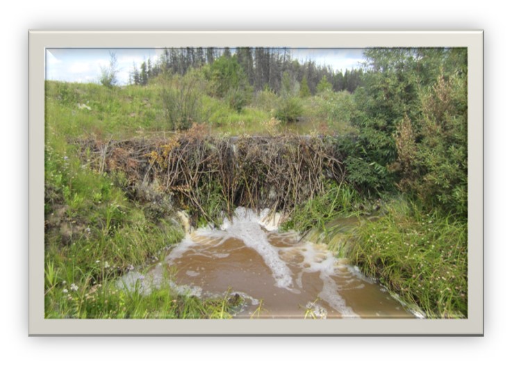
Photo above of a beaver dam on a stream, which is a barrier
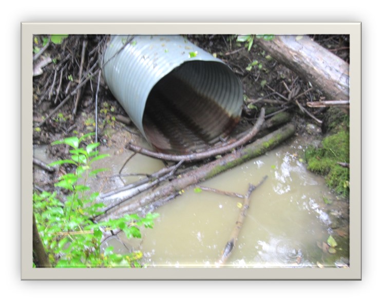
Photo above of an improperly installed culvert: This steel culvert is a fish passage barrier (not properly embedded and undersized).
Connectivity (Part 2)
Please click on this link to view a video about connectivity
A stream should be able to freely transport sediment and LWD downstream and permit the movement of fish up and downstream to access the channel and habitat features.
QUESTION: What are the signs that an accumulation of LWD should be considered a blockage and break in the connectivity to fish, sediment and debris movements?
ANSWER: LWD accumulation that span a channel are not always a blockage. We need to be diligent to confirm that it is a blockage, by looking for:
- Water is mostly (>2/3 of flow) forced over or around the accumulation
- The channel has eroded wider than normal
- There is active sign of erosion to the banks because of the water diversion
- Crossings structure intakes are blocked
- Crossings structure outlets are becoming perched
- Extensive sediment and debris buildups immediately upstream of the accumulation, embedding the channel/crossing structure
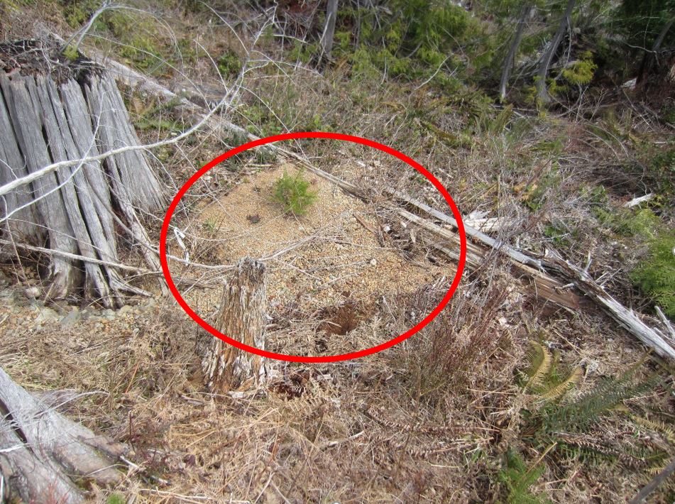
Photo Above of Dewatered Channel – excessive sediment delivery causing channel to appear ‘dry’ even though there is water flowing above/below the accumulation

Photo Above of Culvert blockage – LWD has plugged this box culvert (note fine sediment quicksand)
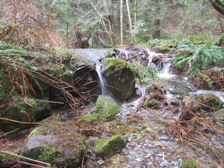
Photo Above of Culvert Outlet – a culvert is plugged and water is diverted over the road, incising the channel and we now have a fish-passage barrier
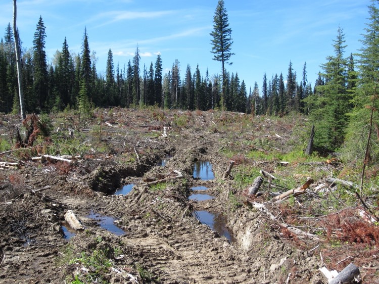
Photo Above of Overland Flow Diversions – severe rutting within the 10m riparian zone has intercepted and diverted overland flows away from the stream
Locating a Reach to Assess
Locating a Reach to Assess: To locate your field sampling reach, there are a few considerations to follow. You will reference your map for the planned, priority stream for stream class and review the treatment planned alongside this stream. Locate this stream in the field and then verify that the stream is still eligible to sample. You will review its width and treatments along the reach.
Confirm that the stream length within or adjacent to the block is also long enough to qualify for a sample. The block is defined as the opening ID boundary as seen on the site map and not merely the harvested area. To be eligible, the stream reach length must be 100 m, or a distance equal to 30 channel widths, whichever is greatest. For streams situated adjacent to the block, confirm the stream also meets the adjacency criterion of the entire eligible sample reach being parallel to and within 2 RMA widths of the opening ID boundary. The 2 RMA width measurement differs by stream class. If there is a road crossing on the sample reach, we locate the entire sample reach downstream of the crossing, below the estimated right-of-way clearance and disturbance.
Next, confirm that the reach you wish to sample is homogenous in stream class, harvest treatment and channel morphology. This can be done by walking the length of the reach for the required reach length. Note that the harvest treatment can differ from one side of the stream to the other. However, the treatment on each side of the stream should be more or less the same along the whole reach. Stream reaches that go from one distinct type of retention to another on the same side, or which are partly in and partly out of a block, should not be assessed as one reach. Similarly, if the stream was S6 (<3m width) at the start of your walk, but then downstream there is another stream converging and now it becomes an S5 (>3m width) then the reach should be re-positioned to be wholly S6 or S5 but not both.
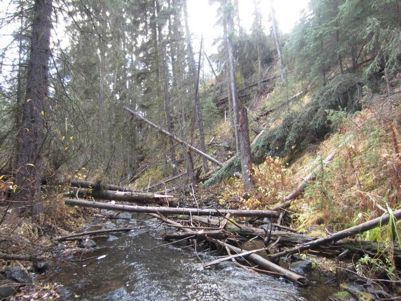
Photo above: The stream is adjacent to the cutblock up the slope on the RIGHT. To be eligible to sample, cutblock boundary means the legal opening ID boundary. If the stream is within 2 RMA’s (measured as SLOPE DISTANCE) of this boundary, then it can be considered for sampling.
Laying Out the Reach for Assessment
Laying Out the Reach for Assessment: To collect the necessary information that will support the RREE assessment, the assessor(s) must first locate sampling transects along the reach. To do this, the sample reach is equally divided into 5 segments by the establishment of 6 point transects. To establish the point transects, take the reach length and divide by 5 to get the interval distance between transect stations. A reach of 100m will have transects established every 20m (100m/5 = 20m).
At the start of the reach (transect #1) you will tie a flag and write on this flag the Point of Commencement (POC) information: FREP Riparian Sample #, POC, Date and initials of the team. Then each subsequent transect station is flagged and the reference transect # and/or traversed distance away from the POC written on the flag.
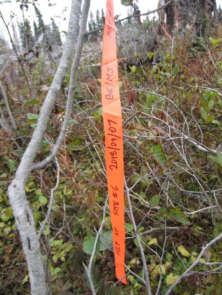
NOTE: To assist in determining the channel’s gradient, it is a good practice to hang the flags at eye level while standing on the channel bed.
LESSON 4: Self-Check Questions
1. If a stream’s channel depth is 25cm at bank full, but you come when the stream is totally dry, there can be no DEEP POOLS because they are dried up.
2. If you have a stream that is 10m in width and you have a timbered buffer of 25m along 200m of this stream and then 100m of stream with harvesting within 5m of the stream, you can assess the 200m + 100m as an eligible 300m reach
Answers
1. False – Pools are a channel scour feature and always evident; at the time of your visit, their presence & determination of being DEEP is not dependent upon water level.
2. False – the 10m wide stream MUST have a homogenous reach (e.g., same treatment) of 30 x channel width (300m for a 10m wide stream). The 2 treatments are different and neither are 300m in length – go find a different stream to sample.

